Saturday, January 25, 2014

Took a little "brake" from the windshield since Jeffrey headed back to New York, I needed something I could do without help, so I finished up connecting the brake booster to the pedal. The brake booster came with a 3/8" - 24 right hand thread and the brake pedal rod on the Wrangler booster was 1/2" with a taper and ball on the end. I assembled the new booster to the firewall and measured to the centerline of the pin on the brake pedal to the end of the 3/8 shaft on the booster. The Wrangler rod was then cut to that length. The brake pedal on the CJ was uncomfortably and unnecessarily high since it was originally manual and
was now power assisted. I thought it would be pretty cool to have an adjustable pedal height. Not like on some newer vehicles where you can adjust it from the dash but at least one time adjustable to the driver and then leave it set. So since the brake rod was 1/2" I decided to thread it 1/2" - 20 left hand, then make up a coupler similar to a turn buckle that after it was assembled the coupler could be turned to adjust the height of the pedal. 3/4" steel hex stock was used and tapped one end 3/8" - 24 right hand
and the other end 1/2" - 20 left hand. I had a tap from my bicycle days but needed a die to thread the brake rod. MSC Industrial Supply came through on that one. https://www.mscdirect.com/product/03844214?rItem=03844214 A new 3/8" lock nut was supplied with the new booster but I had to make up a left hand one for the brake rod end. Assembled everything and adjusted the pedal height to suit and cinched down the lock nuts. Jeffrey painted the
master cylinder and lid before he left but was not pleased with the black lid and the fact that it gets scratched when ever the clamps are slid into place, so a chrome one is on the to get list.

Friday, January 24, 2014

Made a killer buy on a Wrangler windshield frame from our local u-pull. http://www.joesusedautoparts.com/EZPull.html Jeffrey had known about it weeks ago so we weren't sure if it would still be there, but it was. The reason it was still there was because nobody could remove it. Damn rusted torx head bolts. As we got to it 2 other guys came walking up to it with intention of trying to remove it. They had tried the previous day and after stripping the heads on all the torx bolts gave up but
came back with no additional tools. Don't know what they were thinking. Anyhow, eye contact was made and they decided to leave it. I guess we had a bigger tool box. We had brought along a Snap-On impact driver http://buy1.snapon.com/catalog/item.asp?item_ID=631500&group_ID=674820 knowing it was going to be a problem, but with the stripped heads we had no success. The windshield was surprisingly rust free with a very nice tinted glass, wiper motor and sunvisor brackets. On closer inspection we noticed that the hinges were almost broken off from a previous owner trying to fold it
down with rusted fast hinge pins. So there was no   use in trying to save them. The only other problem was that the roll bar extension pipes fastened to the windshield frame were also attached with stripped torx. If we could get them off then we could finish braking off the hinges and be on our way. Just so happened I brought along a saw. Not a hack saw but a vintage Allway saw. This used to be my grandfather's but comes in handy but was small for the task in hand. Where there is a will there is a
way. Well needless to say we took turns sawing our way through the bars. It was cold that day but we were both sweating. Total cost was $55.00. Got it home and applied heat to the bolt heads and they turned right out. Removed the wiper motor and bench tested it, works nice and quiet. Sunvisor brackets came off then the glass. The Wrangler glass is glued in unlike the CJ's that use a rubber seal. This is one reason the Wrangler frames are less prone to rust. Removal of the glass, recommended by a glass
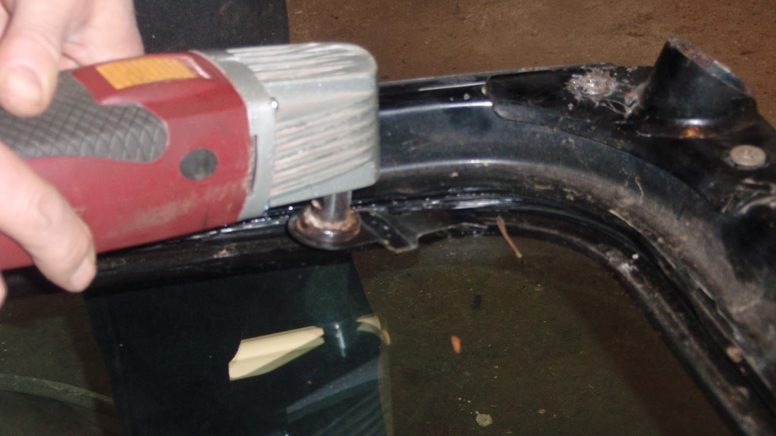
installer was to use a wire, or they would do it for $45.00 Nah, we can do this. Started out with a utility knife but was taking too long so I broke out the trusty oscillating multi function tool from Harbor Freight. http://www.harborfreight.com/power-tools/oscillating-tools/oscillating-multifunction-power-tool-60428.html Held flat against the glass and cut into the adhesive made short work of it. We had one complete hinge from the CJ and a lower half along with the two upper half's from the Wrangler.
A complete pair was needed for mock up so we clamped the two broken half's on the welding table, using a pair of dividers made sure the holes spacing was correct then Jeffrey welded it together. Positioning the assembly in place on the fiberglass cowl revealed that the cowl width was about .330 narrower than the steel body. 2 shims were milled to .165 to fit behind the hinges to take up that space and tack welded to the hinges. A 1/4" thick strip of wood was layed between the cowl and bottom of
the windshield frame to take up the space for the rubber gasket then clamped into position for drilling. Before drilling we will hang the doors and set the top on to make sure everything lines up. A door was temporarily held in place and found fitment to body was dead on. An attaboy to Shell Valley. http://www.shellvalley.com/index.cfm/page/ptype=results/category_id=8/mode=cat/cat8.htm A steel windshield frame was chosen for the strength. Have heard some horror stories about glass popping out when using a soft top. In fact Shell Valley will caution you on this.

Thursday, January 02, 2014

Alright, part 2 of the center console. Fabrication methods will be the same, but this round we will have a solid rear arm rest section to reference from. The rear section is 7" wide, this give ample storage and possibly 2 cup holders along with enough room to access the reclining knobs which are now in the center since we swapped drivers seat with the passenger seat for roll bar clearance. 7" isn't quite enough width to mount (3) 2 1/16" dia. gauges and a radio, so we widened it to 10" were it meets the
dash. This also helps to eliminate the boxy look. (I tried to talk Jeffrey into using military ammo boxes, but that didn't fly. If we were building a rat rod it would have been a go.) Anyhow the same procedures were used to mock up the sides and contour them to the floor and then transfer to the plywood. Angles from the 7" width to 10" was verified on the workbench and cross pieces cut and dadoed in. Test fitted the unit before gluing to make sure everything was honky
dory. http://www.urbandictionary.com/define.php?term=honky%20dory 2 pins will be used at the junction of the front and rear pieces (now held by a vise grip) for location and the front will be bolted down like the rear. The forward section protrudes under the dash to make room for a radio, but caused a problem with the heater outlet for the CJ which is directed straight back. One for a 1987 to 1995 YJ has an outlet that will bolt up to the CJ heater box but is directed to both sides. J C Whitney also
carries this item. http://www.jcwhitney.com/omix-replacement-floor-heater-duct/p2002935.jcwx along with other sources. The top of the console will be constructed out of plywood also along with sheet metal, painted to match the dash. The transition from the vinyl sides to sheet metal top will be hidden by a 3/4 x 3/8 steel or polished aluminum strip running the whole length on both top edges. We'll cover that fabrication later.

Wednesday, January 01, 2014

Wood working skills aren't usually associated with automobiles (unless your building a Woody station wagon) but they can come into play with interior applications. In our case the center console. I am going to break this project into 2 posts (rear and front console) for the sake of space and pictures used. We decided to tackle the rear arm rest section (lockable compartment and mandatory cup holder) first. Wood of choice is 3/4" cabinet grade birch plywood. Here you have a couple of choices. A
U.S. made grade and an off shore brand. We got ours from Scott Millwork in Cressona Pa. http://www.scottmillwork.com/ I prefer dealing with private local companies if possible, the service tends to be better. In this case we were told up front that the off shore brand does have some flaws and in no way compares to the U.S. brand. I had used some of the off shore for a laundry room cabinet project with satisfaction, but working with smaller sections for this console the U.S. brand would have
been a better choice. Since it will be covered with vinyl the voids and imperfections will be hidden. Price difference was about half. On to fabrication. Jeffrey used cardboard as a template and mocked up what he had envisioned. He made it a bit higher than needed, that way the floor contour could be cut a little at a time. This was done by using a set of dividers with the points held vertically to the floor with the side of the console in position then scribe the floor shape on to the cardboard. This was then
transferred on to the plywood. After both sides were established and the height was correct end pieces were dadoed into the sides. Cutting a dadoe helps to align and square the pieces and makes a stronger joint. Carpenter wood glue, clamps and #3 finishing nails held it all together. This makes for a very structurally rigid assembly. Two metal L brackets are used to fasten the rear of the console. The front part will be pinned to the front console section for easy dis assembly. Tops for the arm rest and cup
holder will be made later when he decides on one or two cup holders. Taking the time now to make sure driving conditions are comfortable is why we went with steering, seating, shifter then console fabrication in that order.


Now that we have the seats firmly located, it was time to shift gears and move on to the shifter location. We picked up a B/M ratchet shifter from our good buddy cleaning out his stash and Jeffrey preferred it over the previously acquired Hurst Pro-Matic 2. The B/M supplied T-handle just wasn't comfortable with the reverse lockout so a round 8 ball was substituted which made it alot more ergonomically friendly. Whether it
will stay or not remains to be seen, but definitely a round knob will be used. A mount needed to be fabricated to position the shifter at a comfortable height along with front to back and side position. Once height was established we then concentrated on front to back and side position. A 1/4" steel plate was cut out for the base, tapped for 1/4 - 20 bolts and the shifter bolted to it. Tapping the mounting holes allows us to eliminate using nuts which would be awkward to remove and install after the console was built around it. We needed L brackets welded to the base to establish height and to mount to the transmission tunnel and since I hardly throw anything away the feet that we cut off the Recaro seat base were just what we needed. They even had the holes already drilled into them. (See we recycle.) So side to side positioning ended up favoring the driverside therefore the console will have to be built around that. 3/8th. bolts were used to fasten the whole assembly to the transmission tunnel. Now on to the console.